Build Detailed Meshes Through Image-to-3D Model With Smart Mesh Generation
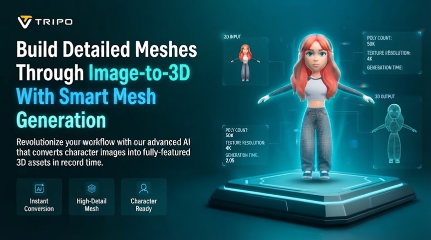
Image-to-3D modeling can turn a visual reference into a lightweight, editable three-dimensional mesh within seconds. This approach can support concept exploration, interactive assets, early visualization, and other workflows where manageable geometry matters. Tripo 3D combines image-based modeling with options for topology, texturing, refinement, rigging, and export. Smart Mesh focuses on structured, optimized geometry rather than the extremely dense meshes associated with high-detail modeling workflows. Its default output is around 5,000 faces, while supported polygon ranges can vary with topology settings.
Understanding Smart Mesh Generation Speed
Smart Mesh is designed for lightweight geometry and short generation cycles rather than maximum polygon density. Tripo describes Smart Mesh as generating game-oriented, low-poly assets in seconds, with approximately 5,000 faces as the default output.
In AI 3d model generator, the generation speed can still vary according to the selected options, input image, workload, and processing requirements. The initial mesh represents one stage of the broader asset workflow. Additional operations such as texturing, refinement, rigging, animation, and export require their own processing time. Therefore, rapid mesh generation should be viewed as an iteration advantage rather than the duration of the entire asset-development process.
Preparing Images for Smart Mesh Reconstruction
The quality of an input image within image to 3d model can influence how effectively the system interprets the subject’s structure. Clear silhouettes give the reconstruction process stronger visual information about proportions, contours, and major forms. Simple backgrounds can also reduce visual interference around the primary subject. Excessive shadows, occlusion, clutter, and unusual viewing angles can make some structural details harder to interpret.
When an object contains important features that remain hidden from one viewpoint, multiple images can provide additional structural information. Tripo’s Smart Mesh workflow supports single images as well as multiple views for modeling.
Steps to Build Detailed Meshes Through Image to 3d Model
Step 1: Start a Fast Image-to-Mesh Workflow
- Begin by opening Tripo 3D and signing up for an account. From the vertical left menu bar, go to the “Model” tab.
- Find the “Generate Model” menu and choose “HD Model” to start with the detailed generation workflow.
- Select the “Image to Model” tab. Drag and drop your source image into the upload area. You can also click “Upload” and choose the image directly from your device.
Step 2: Set Mesh and Generation Controls
- In “General settings”, customize “Geometry and Texture” according to the detail you need. Enable “Ultra Mesh Quality” when you want a more detailed and realistic mesh.
- You can allow AI to generate the model’s geometry and texture by turning on the “AI Complete” switch in the Geometry & Texture panel. Alternatively, enable texture generation and choose your preferred “Texture Quality” from the available 2K, 4K, and 8K options.
- Enable “PBR” to give the model accurate material reflective properties.
- Choose between “Quad” and “Triangle” topology to define how the mesh is structured.
- Set the polycount according to the amount of geometric detail you want in the final model.
- Members can try the “Generate in Parts”, “8K Texture”, and “Privacy” options in the Members Only area, with “Trial x1” available per session. Note:“Generate in Parts” requires separate point billing.
- Select a model from the available options. Tripo supports “V3.1”, “V3.0”, and “V2.5”, each offering different levels of generation quality, stability, and suitability for specific scenarios. Note:“V3.1” may take longer to generate results.
- After reviewing your choices, click “Generate Model” to begin the generation process.
Step 3: Review the Generated Mesh
- After generation, you can inspect your model using various display modes. Choose from Wireframe Mode, White Model View, Texture View, Shader, or HDRI. You can also select “Refine” from the bottom menu to enhance your design.
- Use “Environment Settings” to change the scene around your model. You can manage the camera by selecting “Reset Camera” when needed.
- You can send the finished design for “3D Print” or use “Share” to show the model directly to others.
- When you are ready to save the mesh, click “Export” from the bottom menu. Select the resolution, format, and filename, then click “Export” again to save it locally.
Managing Mesh Detail Without Overloading Geometry
Smart Mesh works by balancing visible form with a comparatively lightweight geometric structure. Polygon density affects how closely the mesh can represent curves, edges, contours, and smaller structural features. Higher counts provide more geometric freedom, while lower counts can reduce memory demands and improve interactive performance.
The appropriate density depends on the asset’s destination and viewing distance. Interactive applications often benefit from controlled geometry budgets, while close-up visualization may require additional surface detail. Texture maps feature in text to 3d model can represent many surface variations without adding equivalent geometric complexity. This distinction helps separate structural detail from visual surface detail during asset preparation.
- Higher polygon counts can represent complicated contours with greater geometric flexibility.
- Lower polygon counts can support interactive applications where memory and viewport performance matter.
- Texture maps can add surface variation without increasing the underlying mesh by the same amount.
- Quad topology can support further deformation and manual editing when those tasks are required.
- Triangle topology can suit workflows where broad compatibility and lightweight geometry are important.
Smart Mesh supports polygon targets across a defined range, allowing geometry density to match different downstream requirements.
Where Rapid Smart Mesh Generation Helps Accelerate Iteration
Short generation cycles make it practical to test different reference images and geometry settings. You can compare how alternative viewpoints influence the generated structure and overall silhouette. Different polygon targets can also show how geometry changes under different performance constraints.
This iterative approach can support early asset exploration without committing immediately to dense geometry. It can also help identify which reference images provide stronger structural information. However, generation speed does not remove the need to inspect the resulting mesh carefully. Each variation can interpret hidden surfaces and proportions differently, depending on the available visual information.
Refining Generated Smart Meshes After Initial Creation
Generated geometry should be inspected before moving into later production-oriented stages. Check the silhouette, proportions, surface continuity, intersections, and openings from multiple viewpoints. These checks can reveal problems that remain hidden when the model is viewed only from its source-image angle.
Texture inspection can reveal alignment issues that are not visible in the geometry alone. Material and unlit viewing modes can help separate surface appearance from underlying mesh structure. Refinement can then focus on the specific areas that need adjustment rather than changing the entire asset.
Retopology or additional mesh optimization may still be useful when a project requires another polygon budget. A lightweight Smart Mesh output can therefore become a starting point for further editing. The required amount of refinement depends on the destination software, asset complexity, and intended use.
Managing the Complete Workflow Beyond Smart Mesh Generation
Image-based modeling is only one part of an asset workflow. After generating the mesh, you can continue with texturing, part separation, rigging, animation, refinement, or format conversion when those stages are required. Each operation introduces different requirements for geometry, materials, compatibility, and file structure.
Part separation can divide complex objects into logical components for more targeted editing. This approach can help when individual sections need to be transformed, adjusted, or exported separately. Tripo also provides rigging and animation features for compatible characters, supporting workflows involving Blender, Maya, Unity, Unreal, and Mixamo.
The final workflow depends on whether the asset will support real-time rendering, animation, visualization, prototyping, or another application. Export requirements can also influence topology, texture settings, polygon density, and file format choices. Planning these requirements before generation can reduce unnecessary changes later.
Conclusion
Smart Mesh provides a practical approach for turning images into lightweight, structured 3D geometry within short generation cycles. Its focus differs from high-density modeling because it prioritizes manageable topology and efficient asset handling. Tripo lists approximately 5,000 faces as the default Smart Mesh output, while supported ranges extend higher depending on topology choices.
The value of rapid generation comes from making repeated experimentation easier. Image quality, viewpoint, polygon targets, topology, and downstream requirements still influence the resulting asset. Careful inspection remains important after generation, especially when hidden surfaces or complex structures are involved.
By keeping Smart Mesh settings aligned with the intended workflow, you can create editable assets without unnecessarily increasing geometric complexity. The result can support prototype-oriented modeling, interactive applications, and other workflows that benefit from lightweight 3D geometry.