What Is the Best Way to Prototype an Electronic System Before Mass Production?

Anyone who has taken a product from a schematic to a factory floor knows the exact moment things get real. It happens right when you order the first batch of physical parts. Software simulations are great for theory, and CAD models always look perfect on a monitor. Hardware requires you to deal with physics, heat, lead times, and suppliers who might substitute a part without asking. Moving straight into mass production without a layered prototyping phase is basically setting money on fire. You need a systematic approach to prove the design works in the physical world before committing to tooling and bulk orders.
Prove the Logic on the Bench
Before you spin a custom circuit board, you need to know the core components actually talk to each other. Engineers sometimes rush this step because they want to see a shiny green board on their desk. Resist that urge.
Get standard development boards for your chosen microcontroller, sensors, and power management chips. Connect them on a bench. This setup will look messy. It will literally be a chaotic web of jumper cables and breakout boards. But this phase is strictly about writing your initial firmware and proving the base concept.
If the I2C bus hangs during a read cycle, you can fix it in software or physically swap a sensor module in ten minutes. Finding out a chip has a fundamental hardware flaw after you order custom boards means losing three weeks and thousands of dollars. Get the core logic running perfectly on the bench first.
Build the First Custom Board
Once the bench model works, it is time to design your first printed circuit board. Don’t try to make it the final production size yet. Give yourself plenty of room. Route your traces with generous spacing and add test points everywhere. You will definitely need those test pads when you are sitting there with an oscilloscope at midnight trying to figure out why a voltage regulator keeps dropping out.
This is where rapid prototyping changes the development timeline completely. You can send design files to a fabrication house on a Tuesday and have five assembled boards sitting on your desk by Monday morning. Use this speed to your advantage. Spin a board, find the mistakes, fix the layout, and do it again. The goal here is to lock down the schematic and the component footprints before you even think about the final product enclosure.
Plan Your Connectors and Cables
Hardware teams often treat cables as an afterthought. They will spend three months perfecting a beautiful four layer PCB and then realize they have no clean way to route power to the main header. Connectors take up physical volume. Cables have minimum bend radii. They also create electromagnetic interference if routed poorly.
If you are building more than a handful of test units, hand crimping your own connectors is a massive waste of engineering time. It is also a great way to introduce random human error into your testing. When you scale up to a pilot run of fifty units, engage a reliable wire assembly service to build your internal cables. Having these made to exact specifications ensures every single test unit is identical. It removes the handmade variables that make tracking down electrical faults impossible.
Address Power Delivery Early
Low power devices are relatively forgiving. If you are building a small battery powered environmental sensor, your main concern is usually sleep current and battery life. But if your system handles real power, the prototyping phase gets much more complicated.
Heat dissipation will ultimately dictate your enclosure design. You have to test how the physical system behaves under maximum load for hours. Testing for a few minutes on an open workbench tells you nothing about thermal throttling inside a closed plastic box.
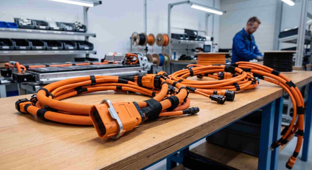
If your product involves industrial motor controls, commercial equipment, or large battery packs, power delivery routing becomes a critical safety item. Sourcing a proper high voltage wiring harness early in the prototyping schedule is mandatory in these fields. You cannot mock up heavy power lines with standard bench wire. You need the actual materials, thick insulation, and physical routing constraints to test for thermal limits and safe clearances.
Verify Component Availability
Engineers love to pick the newest components for a prototype. The datasheets look amazing. You design the board, test it, and everything works flawlessly. Then you send the bill of materials to your factory and find out that your main power management chip has a fifty week lead time.
Your prototype is completely useless if you cannot buy the parts at scale. Sourcing needs to happen concurrently with design. Before you finalize any schematic, check the global stock levels for your critical active components. Stick to parts that have multiple active suppliers or drop in replacements whenever possible. If a component is a single source part with volatile stock history, buy enough of them for your first production run before you even finish prototyping.
Nail the Mechanical Fit
Electronic systems do not live in a vacuum. They live inside plastic, aluminum, or steel enclosures. Once your electronics are stable and your cables are specified, print your enclosure. Drop the board in and see how it mounts. Check if the USB ports and status LEDs actually line up with the holes in the case.
Usually, they don’t. You will almost always find that a capacitor is too tall, or a cable path interferes with a mounting screw. This is exactly why you left room on that early test board. Now you can shrink the board, move the components to fit the rigid mechanical constraints, and order your final pre-production candidate.
Run a DFM Review
Design for Manufacturing is a completely separate phase from functional prototyping. A board that works perfectly on your desk might be a total nightmare to assemble on an automated factory line. Look closely at your component choices. Are you using through hole parts that require manual wave soldering? Can you swap them for surface mount components that a standard pick and place machine can handle in milliseconds?
Talk to your contract manufacturer at this stage. Send them your files. They will tell you if your copper pours are causing thermal relief issues during soldering, or if your components are placed too close to the panel edges. Fixing these physical manufacturing hurdles now will save you a massive amount of money in assembly line downtime later.
Execute the Pilot Build
The final step before full mass production is building a small batch of completely finished units. Usually, this means building somewhere between 20 and 100 devices. Do not build these in your office. Have them built using the exact processes, suppliers, and factory lines you plan to use for mass production.
Take these units and hand them to beta testers or field technicians. You want users who do not care about your feelings or the late nights you spent designing the hardware. Let them drop the product. Let them leave it in a hot truck overnight. Let them mash the buttons in ways you never explicitly intended.
This phase always hurts a little bit. You will definitely find edge case software bugs that only appear after forty hours of continuous use. You might discover a weak solder joint that fails under repetitive vibration. The plastic enclosure might scuff too easily.
This is exactly what the pilot run is for. Document every single failure. Isolate the root causes and push the final revisions to your design files. Once your pilot units can survive the real world without constant supervision and firmware patches, you are finally ready to push the button on mass production.